8 stories
·
1 follower

Why Not? Make Your Own Mobile Phone From Scratch

2 Shares

Instructables has a most excellent project up today — ArduinoPhone — that shows how to make a functional mobile phone using an Arduino UNO, a GPRS shield, a touchscreen shield, a power module, a battery and a 3D-printed shell.

The phone supports voice calls, SMS and a clock app all controlled by the touch screen using virtual buttons and swipes (the code is on github here).

In total, the components will cost you around $170 USD (not including the cost of 3D-printing the shell.)  The project’s home page is here.

Check out the charming video of ArduinoPhone in action:

Read the whole story
dmh43
3932 days ago
reply
Share this story
Delete

The most advanced microwave you’ll ever own

3 Shares

raspberry-pi-microwave

Voice activation, one-touch cooking, web controls, cooking settings based on UPC… have you ever seen a microwave with all of these features? We sure haven’t. We thought it was nice that ours have a reheat button with three different settings. But holy crap, what if you could actually program your microwave to the exact settings of your choice? You can, if you let a Raspberry Pi do the cooking.

This hack run deep and results in a final product with a high WAF. Nathan started by taking apart his old microwave. He took pictures of the flexible sheets that make up the control button matrix in order to reverse engineer their design. This led him to etch his own circuit board to hook the inputs up to a Raspberry Pi board and take command of all the appliance’s other hardware. Because it also drives the seven segment display you’ll never see the wrong time on this appliance again. It’s set based on NTP.

We mentioned you can tweak settings for a specific food. The best way of doing this is shown in the demo video. The web interface is used to program the settings. Recalling them is as simple as using the barcode reader to scan the UPC. Amazing.

Now you can keep that old microwave working, rather than just scraping it for parts.

[Thanks Tom]


Filed under: cooking hacks, Raspberry Pi
Read the whole story
dmh43
3938 days ago
reply
Share this story
Delete

Text editor running on your ARM project

1 Share

bare-metal-elua-text-editor

Tired of flashing your embedded project over and over just to tweak a few values? So was [Karl], so he wrote a text editor that runs on his ARM dev board.

Having trouble wrapping your mind around the need for this kind of thing? He’s actually playing around with eLua, the embedded version of the Lua programming language. In this case the program files are being stored on an SD card. But still, moving that back and forth between computer and embedded project gets old quickly. So he invested the time to write a rudimentary text editor that he interfaces through this terminal window. Above you can see the help screen which lays out all of the applications features. Right now it sounds like the only gotcha for this is the amount of RAM it needs to run. As it stands, the editor will now work an mbed board, but it works just fine on an STM Discovery.


Filed under: ARM
Read the whole story
dmh43
3938 days ago
reply
Share this story
Delete

Update on Our Laptop (aka Novena)

2 Comments and 3 Shares

Back in December, I posted that we’re building an open laptop. The post generated hundreds of comments, and I was surprised there was so much interest.

To be honest, that was overwhelming. Also, there were many who didn’t get what we’re trying to do — as indicated by suggestions along the vein of “use a Core i7 and a fast nVidia graphics chip and sell it for under a hundred bucks and then I’d buy it”.

Rather than try to convince the Internet about my opinions, or suffer the distraction of running a Kickstarter campaign around a very complex and risky project, I decided to hunker down and stick with what I do best — hacking hardware.

Despite the lack of updates here, the project is alive and kicking. All our progress has been publicly trackable via our git repos and on our wiki. There’s also a discussion forum, although I tend to check in only once every month. The board-bringup process and feature validation matrix is noted here, and the list of changes from EVT to DVT is documented here. We also had a little adventure writing code that could calibrate wire delays on the DDR3 bus for a variety of SO-DIMM modules.

The TL;DR version of the wiki documentation is: the board has gone through a major revision, and received a few upgrades that I think really refines its vision.

The FPGA

For me, the integration of the FPGA is a real point of differentiation, so I beefed it up; the DVT version sports a bigger Spartan 6 LX45 FPGA and an upgraded power supply to feed it. I want to be able to use the FPGA to do more coprocessing and data acquisition, and so I added a 2 Gbit DDR3 buffer, connected via a 16-bit, 800MT/s bus. And finally, I want to be able to plug in various high-speed data acquisition modules, so I dropped the Raspberry Pi header and low-speed analog I/Os, replacing the entire cluster with a single high-speed expansion header. The new high speed header breaks out 21 differential pairs plus some single-ended pins. This is sufficient to mate dual 8-bit 500++ Msps ADCs onto the FPGA, making for a fairly decent signal acquisition system.

The Display

I really care about having a lot of pixels on my laptop. So we revised the LCD interface to be easily upgradeable and interchangeable using mezzanine adapter boards. The first adapter board we designed is for a Retina display. We’re now using an LG LP129QE: 12.85″, 2560 x 1700 pixels (239ppi), with a 24-bit color depth. It looks gorgeous.

Below is what the mezzanine board looks like. Dual 24-bit LVDS channels, power, PWM, I2C and USB are fed into the mezzanine via a custom flex cable. The board itself has an LVDS-to-displayport converter chip, and connects to the display via the new IPEX-style micro-coaxial connectors.

I’ve spent some time on the ID, but I’m not ready to share those details with the world yet; however, I will say that the case will use leather and aluminum, and it’s designed to be open, accessible, and easily upgradable to future versions of the motherboard.

In the meantime, we’ve been developing on the system in an “exploded” fashion. The system below shows all the essential elements together and working; keyboard/mouse, LCD, hard drive, mainboard, hosting its own development environment. The desktop environment shown below is stock armhf Ubuntu with our custom kernel, but that is far from a final decision; we’re testing a broad field of distros for compatibility and convenience.

The Router Case

We’ve had a lot of interest from people wanting to use the Novena system as a secure router — the openness of the system is a selling point to many in that space. To that end, we’ve made a conversion case that can house the mainboard alone in a design suggestive of a conventional router.

The 2.5″ hard drive is shown for size scaling.

The lid is anodized aluminum, and most of the screws on the top are decorative. I wanted to buck the design trend of mysterious black monoliths and playing hide-the-screws. Instead, the screws are featured front-and-center, inviting the user to twist them and open things up. “There is no magic in this box. Open me and you shall understand.

Above is the “router” with the lid off and all the ports filled. Probably for the partners I’m working with, we’ll depopulate all of the ports except for the dual ethernet, OTG, and the power jack to reduce cost.

The First Hack (Romulator)

Already the DVT version of Novena has been put to task in helping with our hacking projects. We implemented a “romulator” using the high speed interface, FPGA and DDR3 combo.

The idea is to do real-time, in-circuit emulation of NAND FLASH using the FPGA + DDR3. The FPGA faithfully emulates a NAND device, whose contents can be monitored and modified real-time by the i.MX6 CPU — the DDR3 interface has oodles of bandwidth, and the interface macro provided by Xilinx is configured to provide four virtual access ports to the RAM. In addition, 16MB of the DDR3 is reserved for a logic analyzer-style trace capture of the NAND traffic, so we can dig through the time history of complex transactions and figure out what happened and what went wrong.

A small flexible circuit board adapter plugs into the high speed expansion socket. The board is thin enough to be soldered underneath a FLASH chip for passive monitoring, or directly to the target motherboard for active emulation.

Other boards will be made that plug into the high speed port. My short list includes a high speed ADC board, variants focusing on digital signal acquisition, and PHYs to standards such as USB or HDMI.

The Bottom Line
At the end of the day, we’re having fun building the laptop we always wanted — it’s now somewhere between a python-scriptable oscilloscope, logic analyzer, and a laptop. I think it will be an indispensable tool for hacking, particularly for doing signal analysis which requires coordination across multiple protocol layers, complex trigger conditions and/or feedback stimulus loops.

As for the inevitable question about if these will be sold, and for how much…once we’re done building the system (and, “done” is a moving target — really, the whole idea is this is continuously under development and improving) I’ll make it available to qualified buyers. Because it’s open-source and a bit quirky, I’m shy on the idea of just selling it to anyone who comes along wanting a laptop. I’m worried about buyers who don’t understand that “open” also means a bit of DIY hacking to get things working, and that things are continuously under development. This could either lead to a lot of returns, or spending the next four years mired in basic customer support instead of doing development; neither option appeals to me. So, I’m thinking that the order inquiry form will be a python or javascript program that has to be correctly modified and submitted via github; or maybe I’ll just sell the kit of components, as this would target buyers who know what they are getting into, and can RTFM. And probably, it will be priced in accordance with what you’d expect to pay for a bespoke digital oscilloscope meant to take a position at the lab bench for years, and not a generic craptop that you’ll replace within a year. Think “heirloom laptop”.

Anyways, that’s the update. Back to hacking!

Read the whole story
dmh43
3944 days ago
reply
Share this story
Delete
2 public comments
satadru
3944 days ago
reply
Remember when geeks used something besides apple hardware?
New York, NY
steingart
3944 days ago
Sure do. Also remember wifi adapters crapping out and sound dropping. Geek used to mean yak shave more. It was fun but I'm not sure it's "better"
satadru
3944 days ago
Absolutely. It's a mixed bag of memories.
[deleted]
3943 days ago
In a world where "computing" increasingly means subscribing to a vendor's locked-in end-to-end "solution," we need more points of entry like this one. I so hope some of these efforts take off. Thank you for posting.
jepler
3944 days ago
reply
“…probably, it will be priced in accordance with what you’d expect to pay for a bespoke digital oscilloscope meant to take a position at the lab bench for years, and not a generic craptop that you’ll replace within a year. Think “heirloom laptop”.”
Earth, Sol system, Western spiral arm
emdeesee
3944 days ago
Nobody wants that. I can imagine wanting a python-scriptable oscilloscope, though.

One of Microsoft's Best-Kept Secrets - Python Tools for Visual Studio (PTVS)

4 Comments and 14 Shares
Python Tools for VS

I've talked some about the sweet support for node and PHP in Azure. You can also File | New | Node.js express application in WebMatrix, or run WordPress and get intellisense as well.

"I installed windows just so i can use PTVS" - Comment on Hacker News

But I'm consistently shocked that folks forget about Python at Microsoft. I am a C# person, myself, but the Developer Division at Microsoft loves their languages. C++, VB, C#, F#, etc and they aren't messing about when they get serious about a language.

One of the least-known and most-kick-butt free products we have is PTVS - Python Tools for Visual Studio. Whether you're just interested in learning Python or you're a hardcore PhD who wants mixed-language Python and C++ debugging or somewhere in between, you gotta check this out. (Seriously, the mixed-mode debugging thing can't be overstressed...)

The Misconceptions

  • Microsoft? Python? Oh, it must be all about IronPython, that's dead, right?
    • Fact - IronPython is a community-run project and just put an 2.7.4 alpha out last month. PTVS fully supports IronPython, but the most advanced support is for standard CPython!
  • PTVS needs VisualStudio? I don't have any money.
    • Fact - PTVS, combined with the Integrated/isolated VS Shell is completely and & perpetually free. And with the advent of VS2013, they've combined them into a single installer: https://pytools.codeplex.com/releases (at bottom of page).

This is Real

Here's my VS2013 after installing PyTools (PTVS). I've got IronPython which is Python running under the .NET CLR, but I've also got Django apps as well as a regular CPython or making a new project from existing code.

Python inside VS

You can see that PTVS knows what Python engines I have installed, and I can easily switch between them. Here you can see that VS is refreshing the auto-completion (intellisense) databases for each version.

A list of Python Interpreters

There's also a complete REPL inside Visual Studio for each:

Python REPL inside VS

Developing Django Apps in Visual Studio

Maybe you're a Django (one of Python's Web Frameworks) (Python's Web Framework) web developer, you can use VS to develop your app.

Go File New | Django App, then make a new Python Virtual Environment from the Solution Explorer, and watch Visual Studio freaking installed pip for you (the Python package manager). It's very seamless.

Adding a Virtual Python Environment

Which gives me this:

Python in my VS and I'm FREAKING OUT

Then I right click on "dev" and just like NuGet (except this is Python, so pip) I install django:

Installing Django

Django is massive, so this took a while, but still! And.....I've accomplished Hello World in Django. Well, Hello Django, at least, launched from Visual Studio.

Hello Django

You should feel free to go and run through the whole Django Tutorial if you like and even deploy your app to Azure! You can host Django on a regular Azure Web Site, or a Virtual Machine if you want more control.

You can even interactively debug Python running in Azure on Linux from your Visual Studio instance! Check out Steve do just that at PyCon in this YouTube video.

There's a bunch of great educational and quick start Tutorials on the Python Tools YouTube Channel, they are a great resource to bookmark.

You can attach to remote Python processes over SSL and debug if you like.

Setting up Python Debugging

It's Really Integrated

Let's get real here for a second. Lots of projects plug stuff into Visual Studio. You may have made it this far into the post and be saying "oh, wah wah, this thing sets up some batch files and some syntax highlighting and calls itself a full-featured Python IDE."

Um, no. This is the best of VS and the best of Python and I'm blown away. Check this out. PTVS knows that I'm doing unit testing here and they've integrated Python Unit Testing with the VS Unit Testing UI.

Unit Testing in Python and VS? My heart can't take it!

This is debugging, remote debugging, cross language debugging, tool tips, watches, locals, call stacks, unit testing, full REPL with inline graphics, profiling, cloud publish, best of class CPython support, and so much more.

Nailed it

If you're into Python or knows someone who is, for reals, drink it in and get on board at https://pytools.codeplex.com. Check out their samples. They've got Python talking to Kinect, Python talking to Excel and more. Their PTVS Documentation is really good as well.

Just getting started? Well, go Learn Python The Hard Way.

Installing PTVS

Here's the complete install instrucitons. You need VS, the PTVS, and some Python.

PTVS is free

Finally, explore the Resources and Docs for Python Tools for Visual Studio , including, but not limited to Editing, Refactoring , Unit Tests,
  • Add Import, Remove Imports
  • Interactive REPL
  • Debugging, Remote Debugging for Windows, Linux and OS X
  • Python Environments (and virtual environments)
  • Unit Tests
  • Django, IPython notebook and Azure cloud computing ,
  • Object Browser
  • MPI, IPython, and Cluster Support
  • Kinect for Python and Pyvot - an Excel to Python bridge .

  • NumPy/SciPy for IronPython Quick Start


  • © 2013 Scott Hanselman. All rights reserved.
    Read the whole story
    dmh43
    3947 days ago
    reply
    popular
    3948 days ago
    reply
    Share this story
    Delete
    2 public comments
    jhitze
    3948 days ago
    reply
    Full python support in Visual Studio? Neat.
    Lafayette, IN

    Formlabs Form 1 Teardown

    2 Shares

    I got a Form 1 3D printer!

    It’s the first 3D printer I’ve purchased (technically, I “backed” it). I managed to acquire a pre-release beta unit, as I’m affiliated with Neoteny Labs, one of Formlabs’ investors.

    What’s the first thing I do with any shiny new gadget? That’s right, I take it apart!

    Unboxing

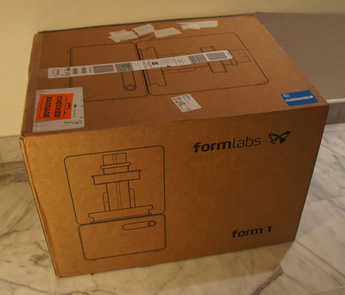
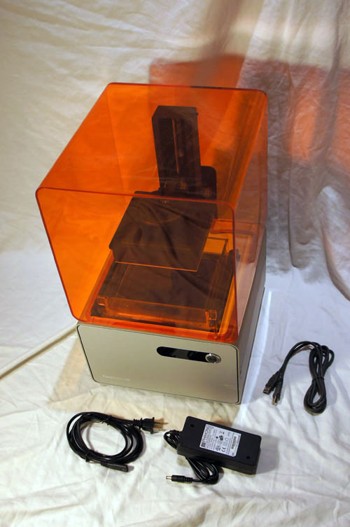
    The complete Form 1 kit consists of three boxes: the printer (shown above), bottles of liquid photocurable resin, and a cleaning station. Many optical stereolithography printers require a cleaning step to wash off the uncured resin; for the Form 1 this means rinsing the part in isopropyl alcohol (the same stuff you use to disinfect cuts, but more concentrated) for a few minutes.

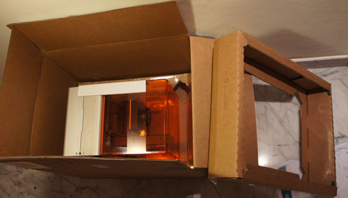
    The packing method, at least for the beta, is styrofoam-free. It uses a pair of thin plastic sheets suspended on cardboard frames to hold the printer in a cradle. For a box that went as checked luggage from Boston to Singapore through three flights, it held up remarkably well.

    The printer box also contains the power supply, cables, and the requisite quickstart guides.

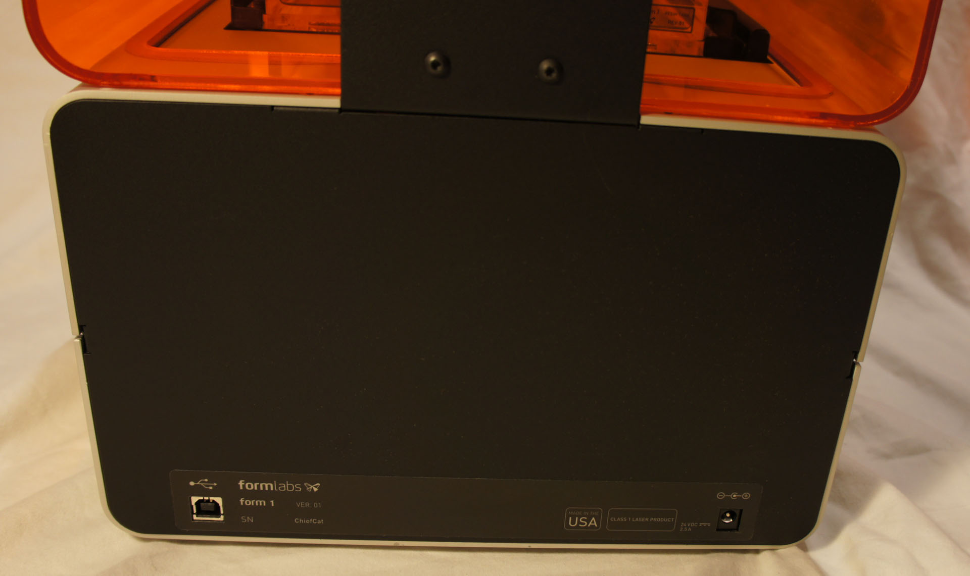
    The serial number scheme, at least for the beta units, is “AdjectiveAnimalname”, so mine is simply “ChiefCat” — hurray for easy-to-read serial numbers!

    Undressing
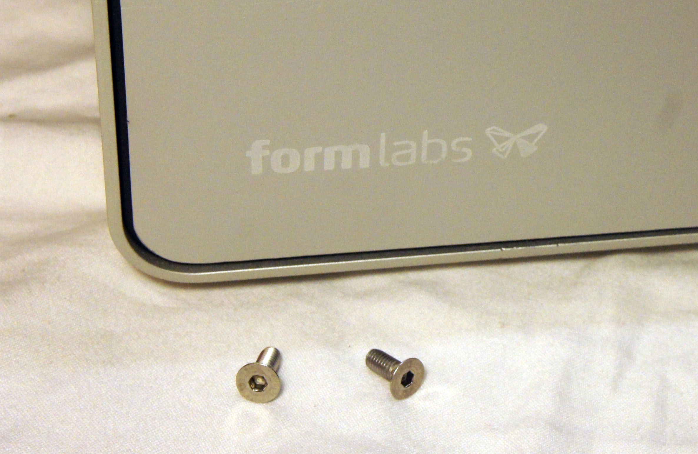
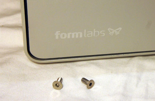
    You need exactly one tool to disassemble the printer: a 2.5mm hex key (or, if you’re a fan of Torx, a T-10 bit). I really appreciate the balance of good design with practicality: it looks good, and you don’t need whacky pentalobe screwdrivers to service it. It does take a bit of elbow grease to undo the screws; but a grippy Torx driver makes short work of the problem without a single stripped screw.

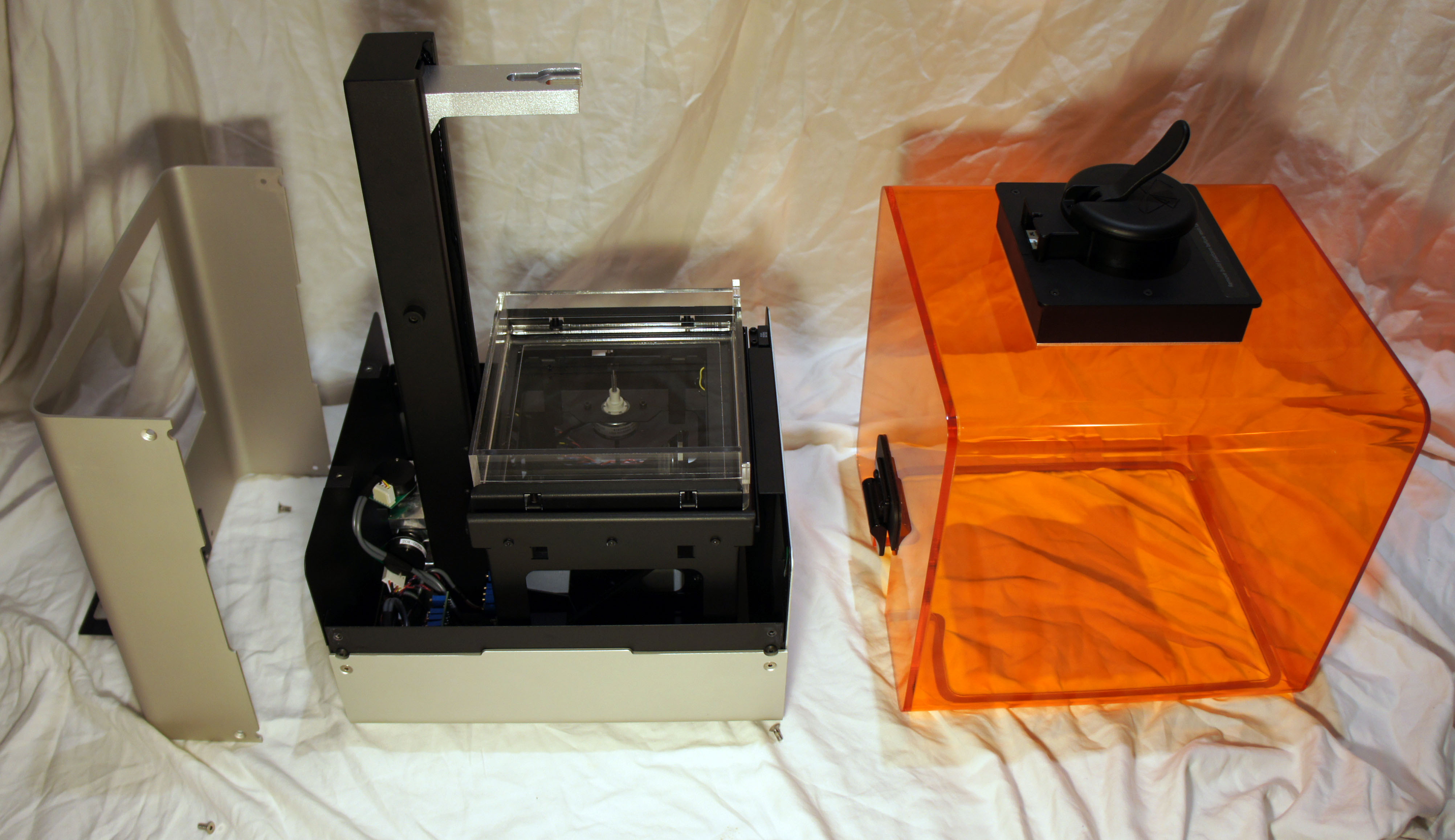
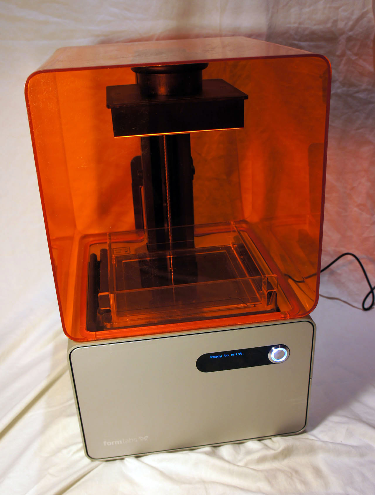
    Two screws release the orange-colored light shield from its hinge, and four screws release the top of the base unit from the frame. The orange-colored shield protects your eyes from stray blue laser light, while also protecting the photosensitive resin bath on the inside from stray ambient light.

    Six more screws (two of which are on the bottom) release the mid-frame from the base. The mid-frame is screwed to the front and back panels, but I didn’t need to remove the panels, as there is enough flexability in the sheet aluminum to slide the mid-frame off. The wiring to the front panel is tidily secured and is exactly the right length to allow the frame to sit next to the base without having to undo any cables — super-convenient for service and debug.

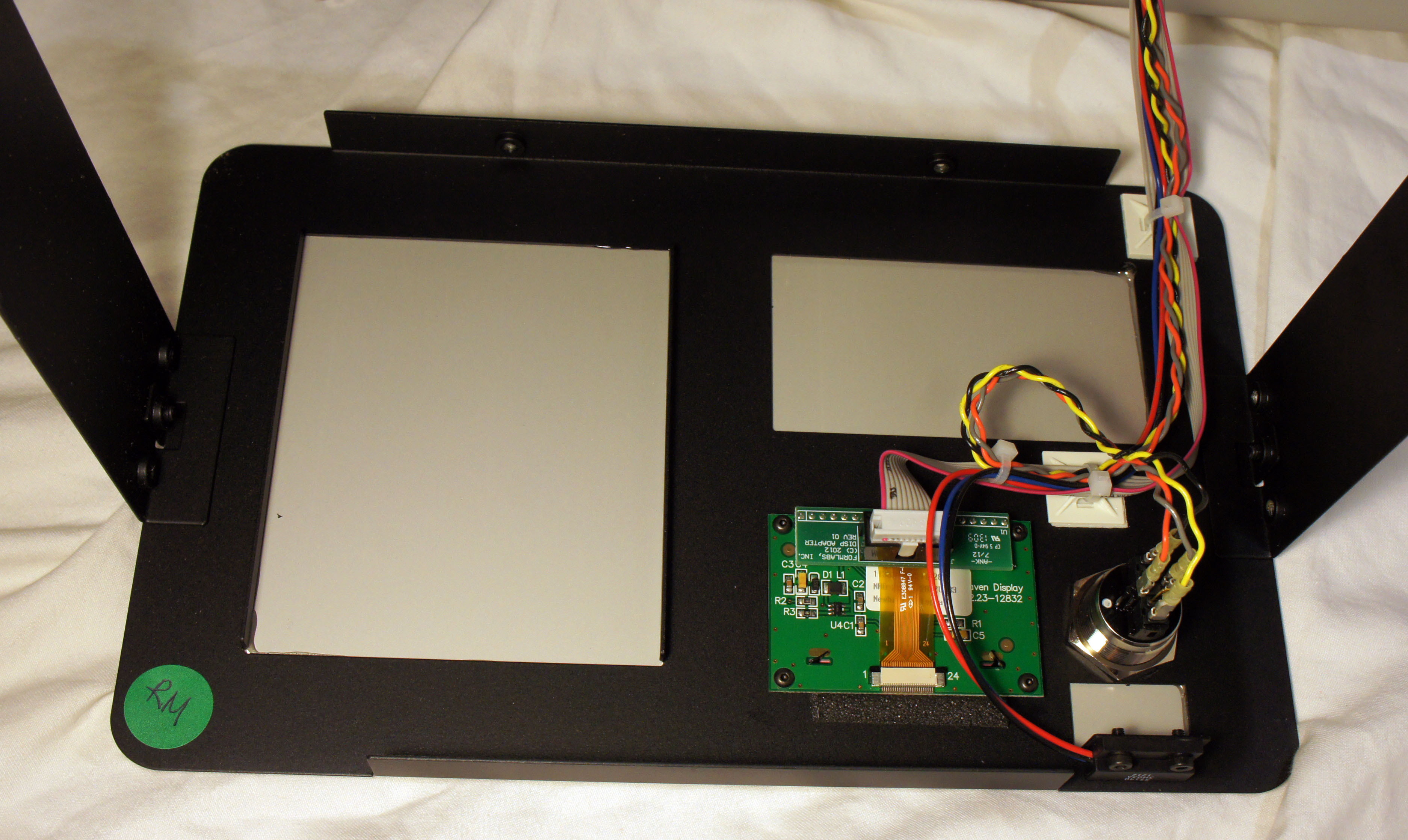
    The inside of the front panel reveals the adapter for the OLED display, as well as the very handsome back-lit power button.

    The Mechanism
    One of the great things about a stereolithography 3D printer is that it uses a laser to cure a resin, instead of melting and extruding a plastic. As a result, the operation is whisper-quiet, and there is no odor during operation — you can put the printer in a bedroom and still sleep at night. To borrow the words of Obi-Wan Kenobi: “This is the 3D printer of a Jedi Knight. Not as clumsy or as random as an FDM, but an elegant tool for a more civilized age.”

    I count four motors in the Form 1: two stepper motors with lead screws, and two galvonometers (which I refer to as simply “galvos”). Let’s tour the printer’s mechanisms, motor by motor.

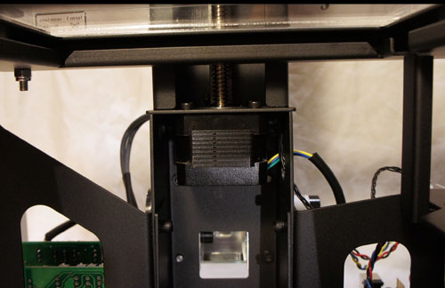
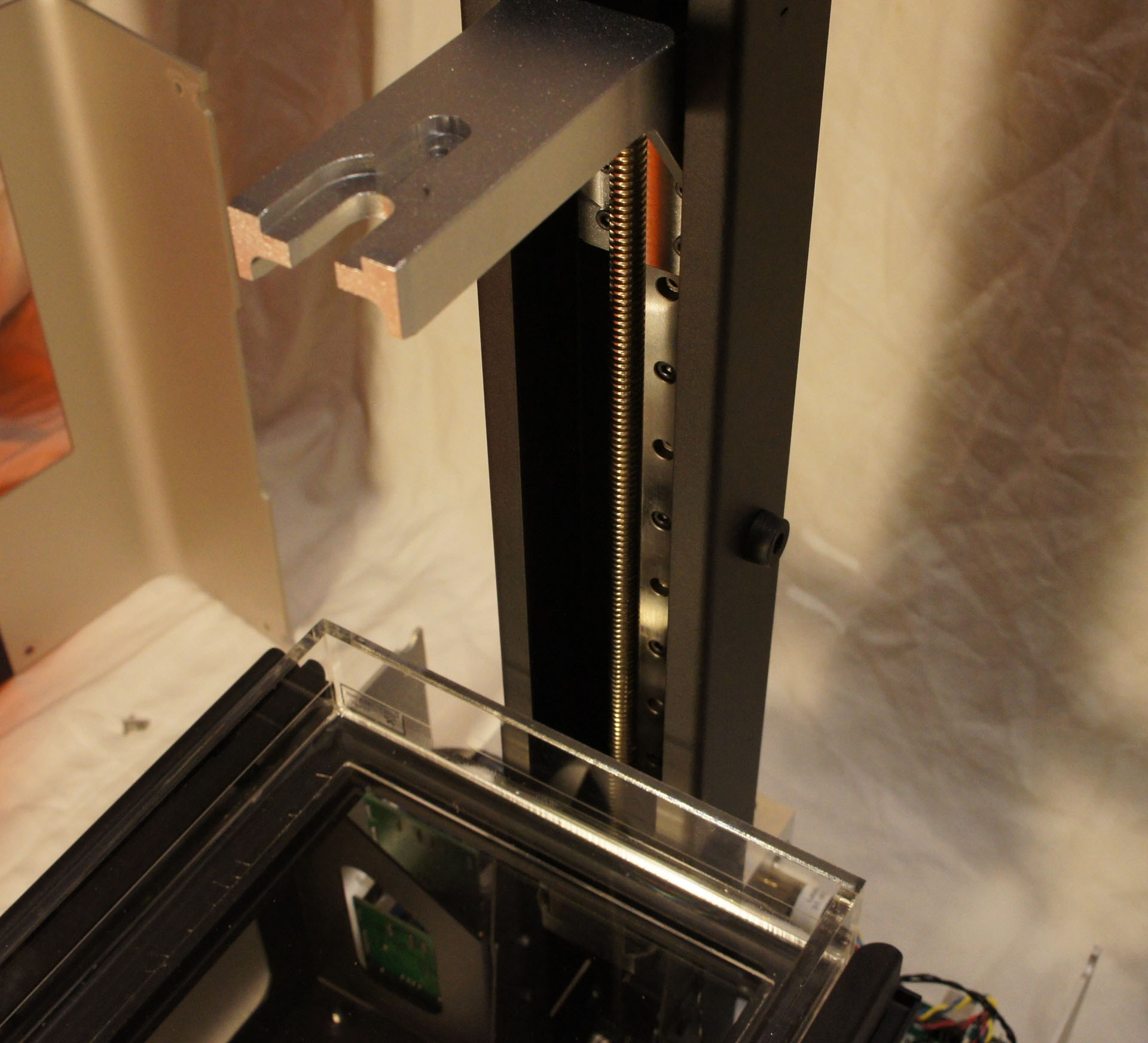
    A large stepper motor with a lead screw running up the spine of the device pulls the build platform upwards. This causes the printed object to appear to “grow” out of the resin bath.

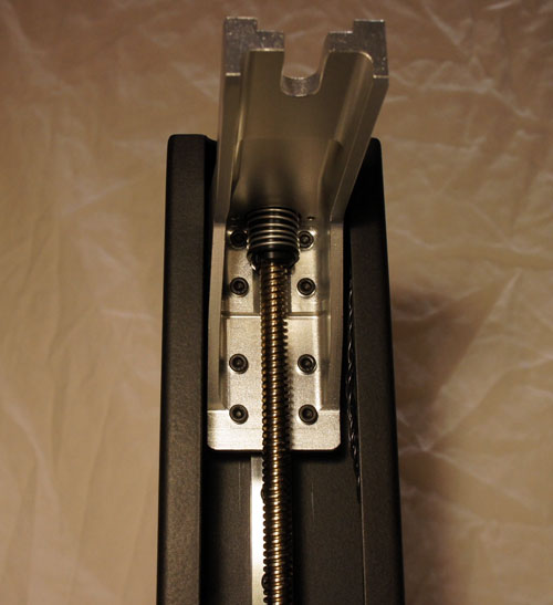
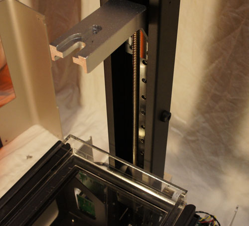
    The build platform is attached to the leadscrew with an anti-backlash nut. The spring in the picture above applies a static force to the leadscrew-nut interface, reducing the play between the two and improving accuracy.

    Every time a thin layer of resin is cured, a second motor performs a “peel” operation by tilting one edge of the resin tank downwards. The peel operation separates the newly formed layer from the bottom of the resin tank, allowing the build platform to move up freely. The leadscrew pictured above is responsible for this action, and it is driven by the smaller of two motors inside the Form 1. The white bearing is fixed to the frame, and the pin connecting the leadscrew to the tiltable resin tank is visible at the top.

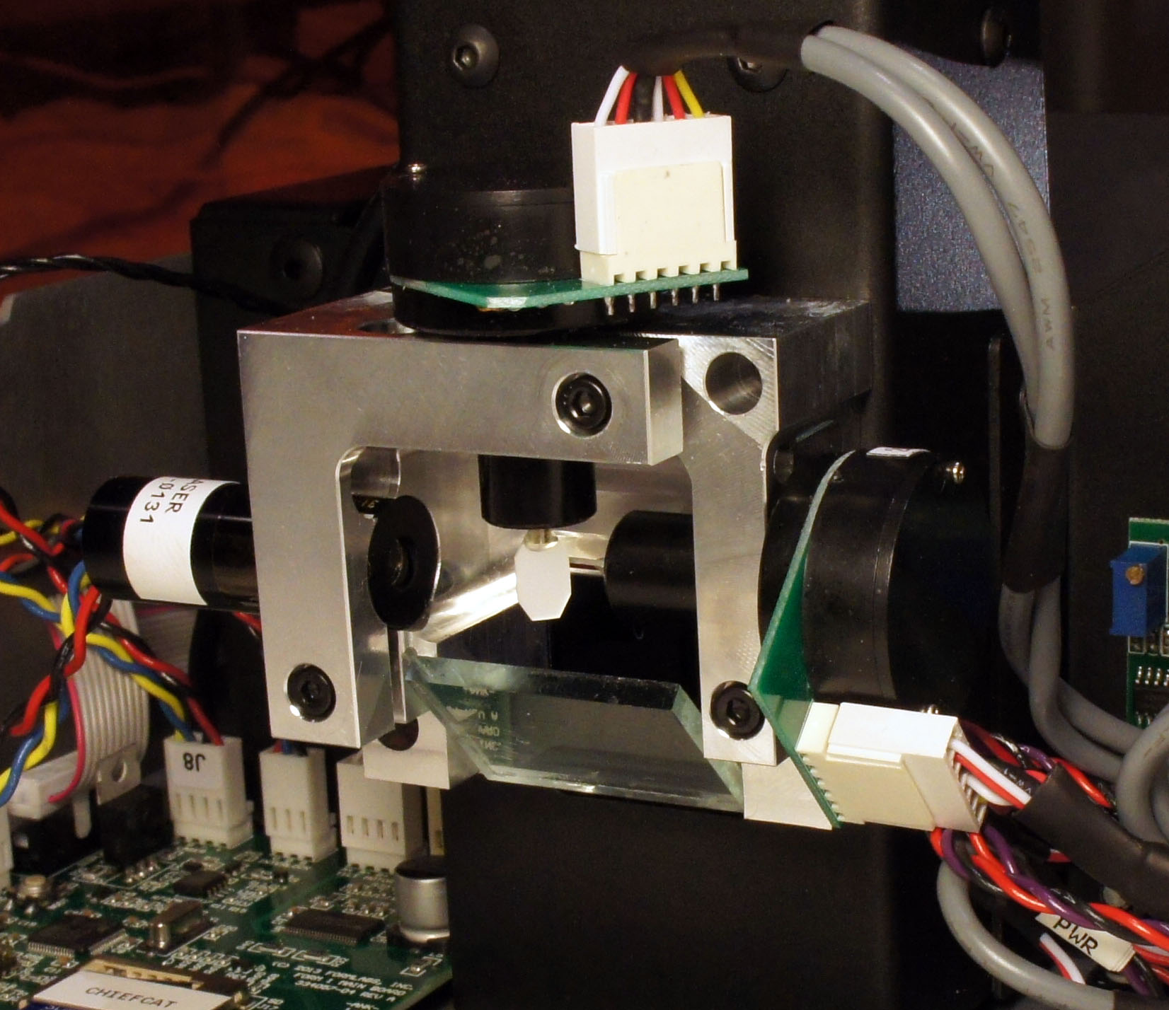
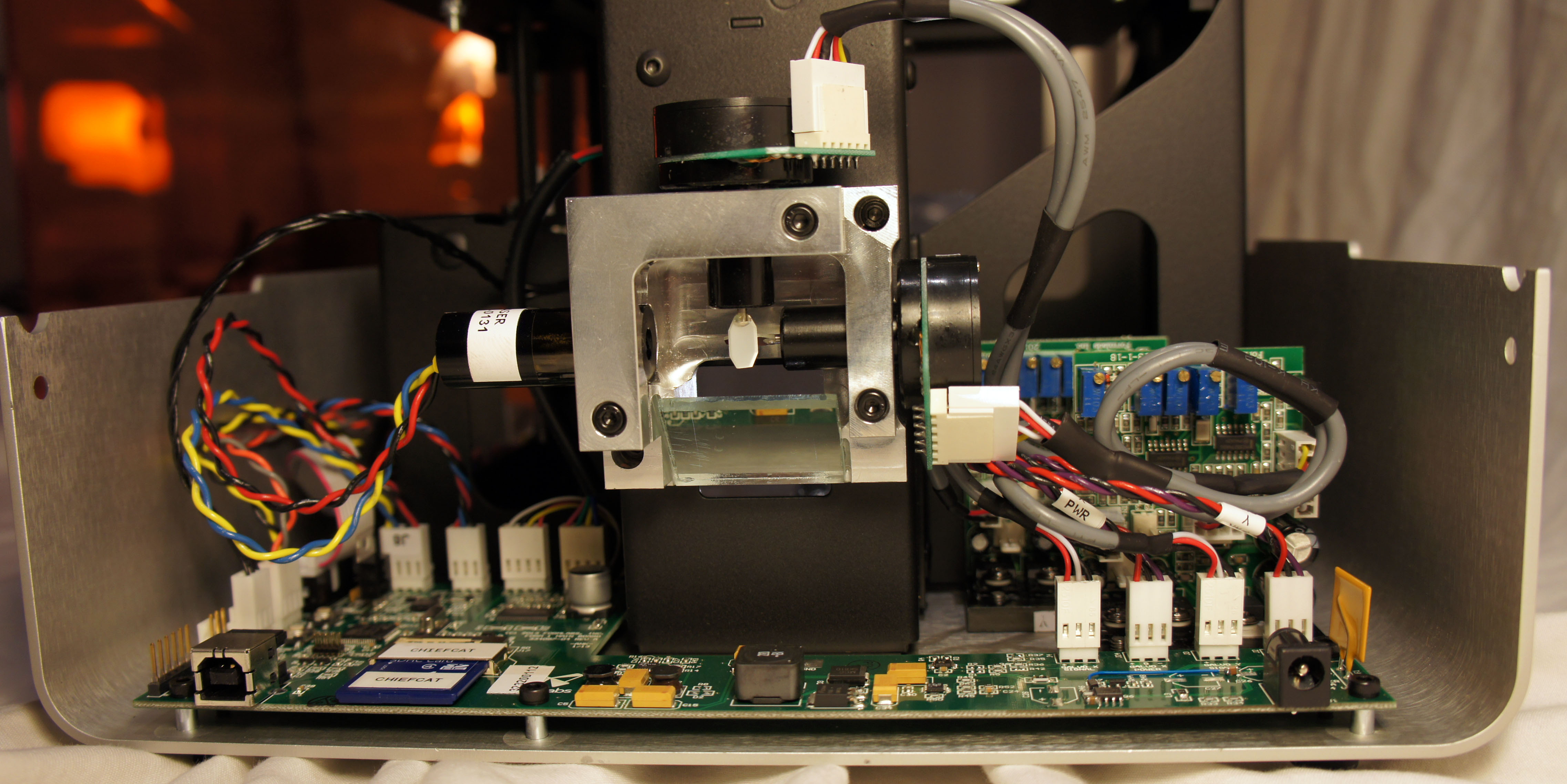
    Ah…and now we peer into the heart of the Form 1! Here are the two remaining motors of the Form 1, the galvos. Galvos are very precise rotational actuators, with a built-in optical feedback loop (take a look inside one). The galvos each have a tiny octagonal mirror attached to their shafts, and are mounted at right angles to each other. One galvo steers the laser beam, entering from the left, along the X axis; then the light bounces to a second galvo that steers along the Y axis. The two working together can thus trace the 2-D vector pattern used to cure a single layer of resin. Below the galvos and laser is a mirror that reflects the light to another, larger mirror that finally shines the beam upwards into the resin bath.

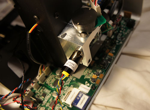
    Above is another view of the laser. According to the safety warning bundled with the printer, it is a 405nm, 120mW violet laser diode (take a look inside one).

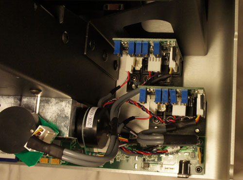
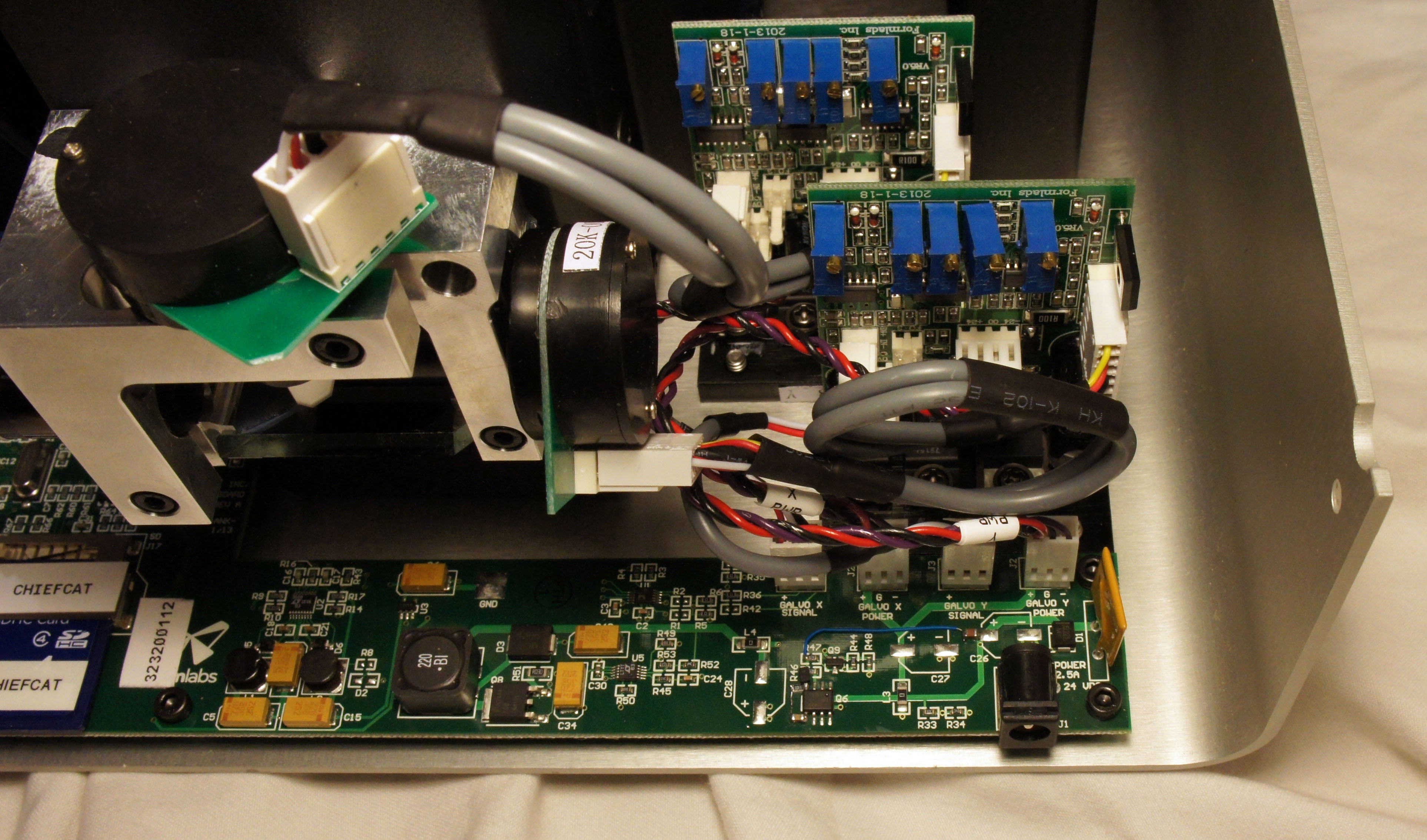
    In order to achieve high performance, the galvo has a sturdy bank of drivers, mounted to the bottom aluminum surface of the case for heat sinking.

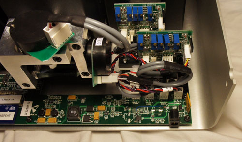
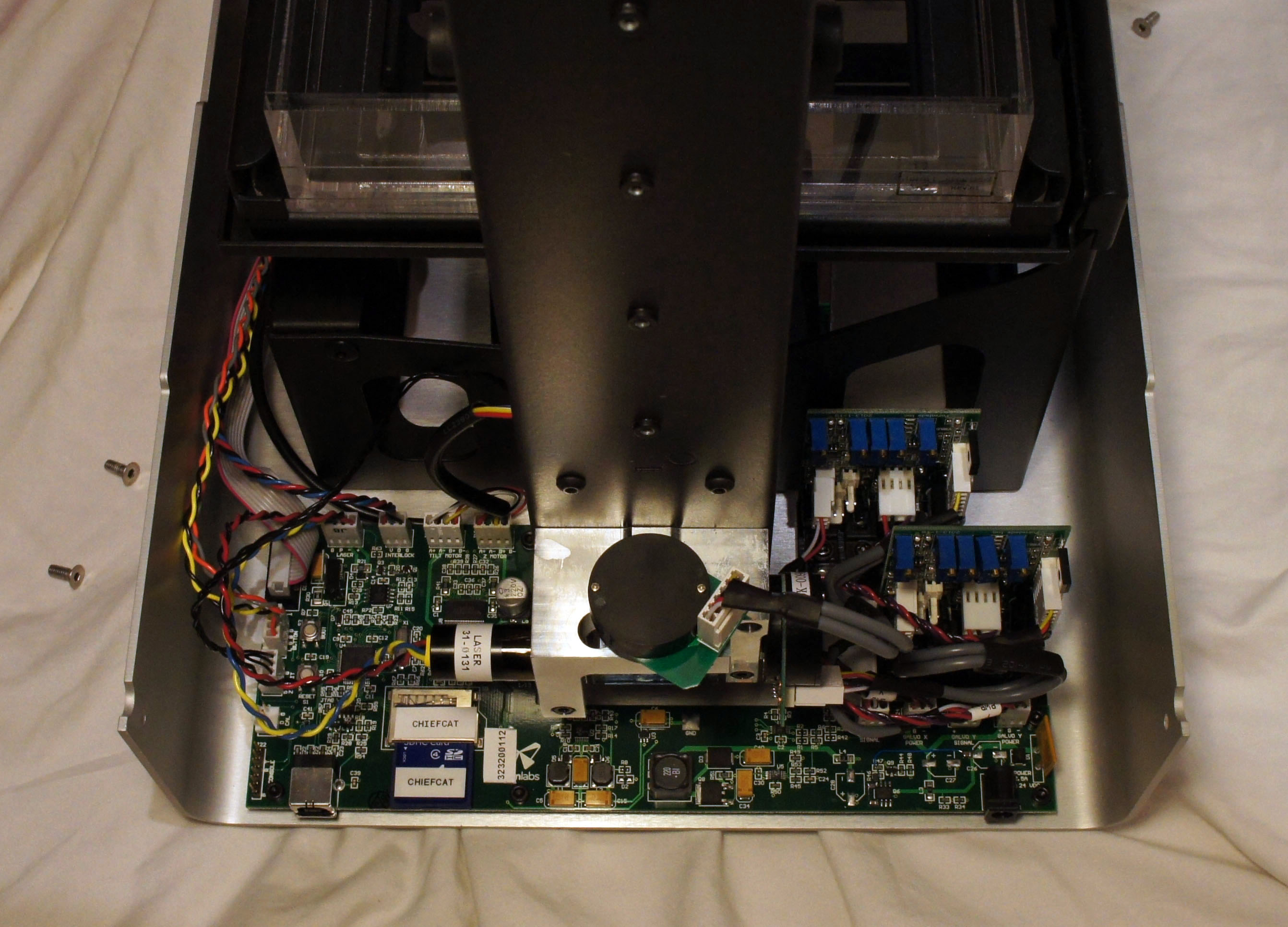
    A slightly different camera angle shows the power input stage of the Form 1.

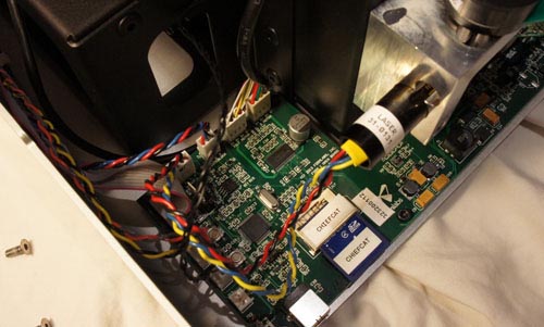
    The main board wraps around the spine of the Form 1 and on the left side are the brains. An STM32 32-bit ARM Cortex-M3 microcontroller coordinates all of the activities inside the Form 1, and it appears that firmware for the device is stored on an internal, captive SD card.

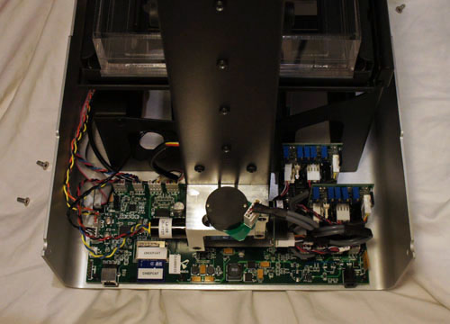
    Above are some photos that give the whole context of the electronics behind the Form 1.

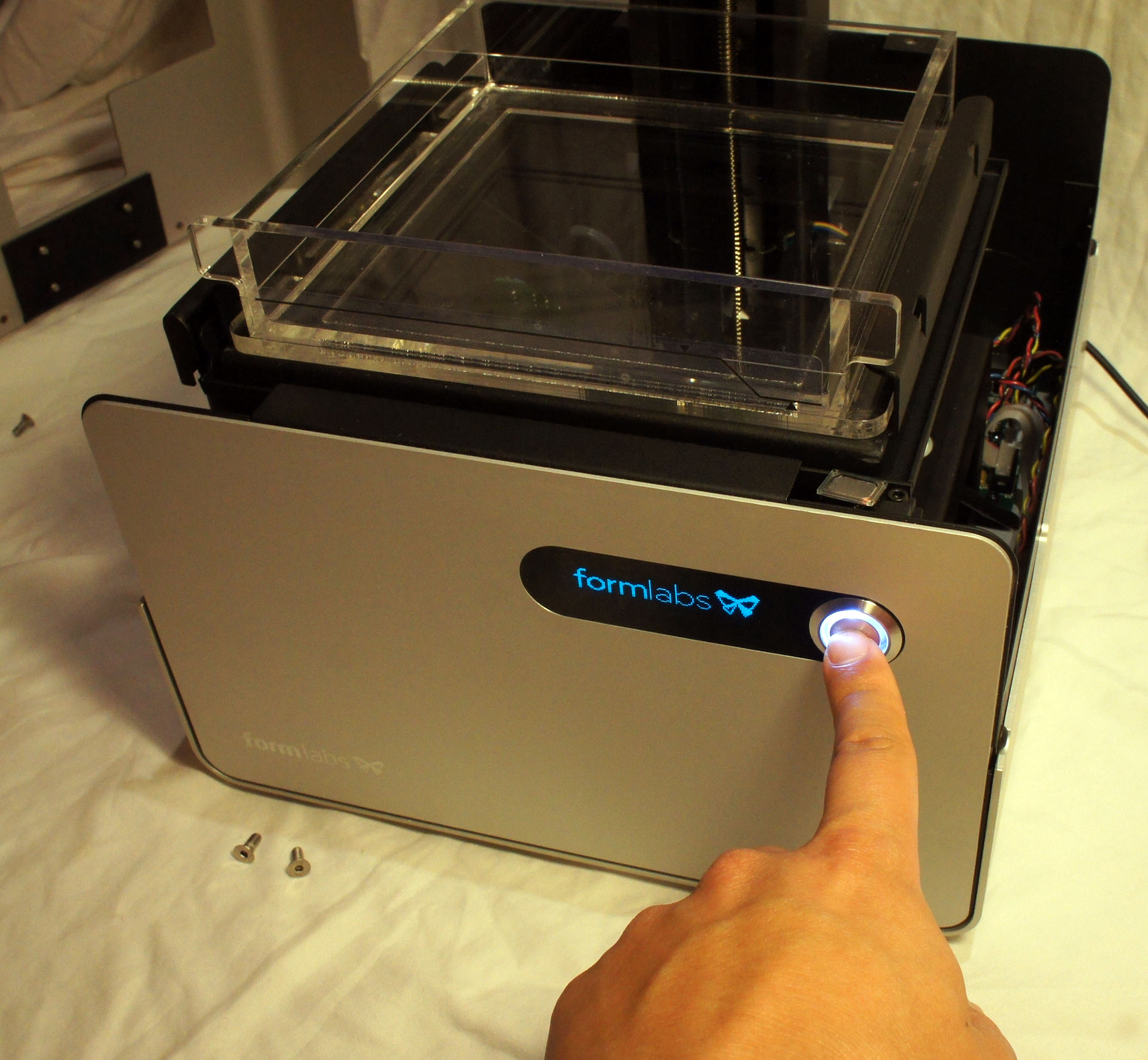
    A hall effect sensor inside the base makes sure you can’t turn the device on when the protective light shield is lifted. But, you can defeat the sensor by putting a magnet on it, as I did above to check I hadn’t damaged anything before putting the whole thing back together again.

    Re-assembly is a breeze — within a couple minutes I have the whole printer put back together and ready to do my first test print.

    My First Print
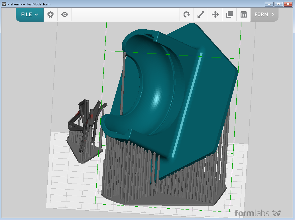
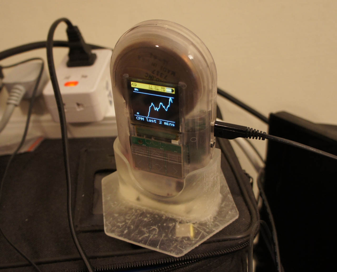
    What’s the first thing I’m going to print? I’m going to download and print a stand, designed by another user (IHeartEngineering) and shared for free, for my Geiger counter!

    The Form 1 comes with a print management software package called “Preform”. It’s intuitive and easy to use; it allows you to place multiple objects on the build platform, duplicate, scale, and rotate. There’s an auto-orient feature that suggests an optimal orientation for supports based upon a DFM analysis. The screencap above is the result of the software picking the build orientation and populating the build supports.

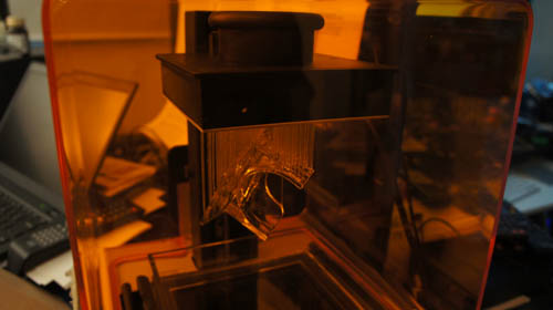
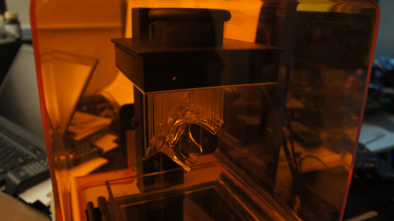
    I click “Form”, and about 10 hours later the print is done.

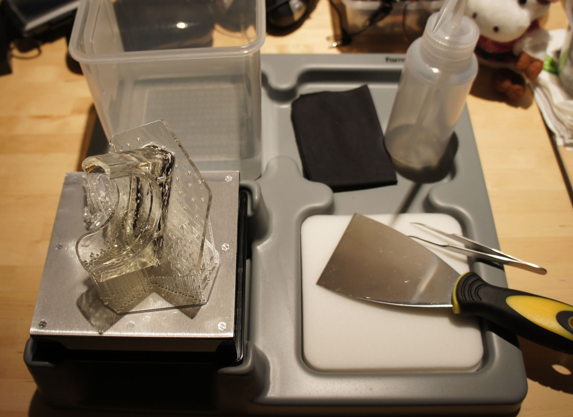
    The next step is to remove the build platform from the printer and bring it to the cleaning station, one of the accessories shipped with the Form 1. Cleaning is necessary to remove uncured liquid resin residue, and it’s recommended to handle uncleaned parts using gloves to avoid getting the goopy resin on your fingers.

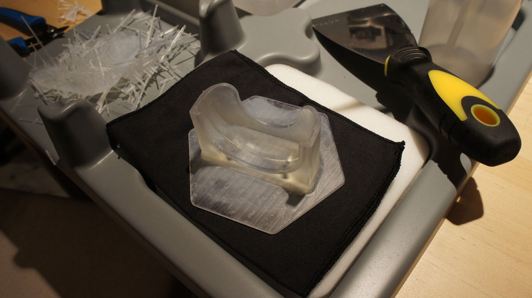
    The cleaning station is thoughtfully laid out, with an area designed to hold the build platform. The kit includes some of the requisite tools to peel the part off of the platform, rinse it, and break off the supports. I supplement the kit with a pair of diagonal cutters for removing the supports, although you can also simply snap the supports off by pulling on them.

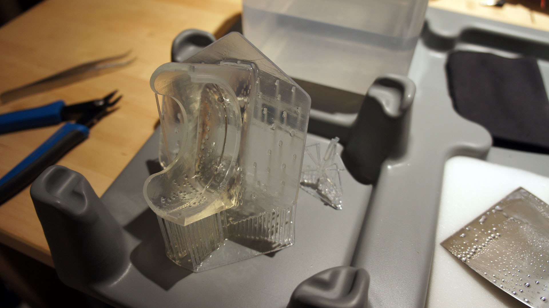
    Two minutes of active shaking in an isopropyl bath, ten minutes of soaking, and the part is ready to be handled.

    I use a pair of diagonal cutters to remove all of the supports in about five minutes.

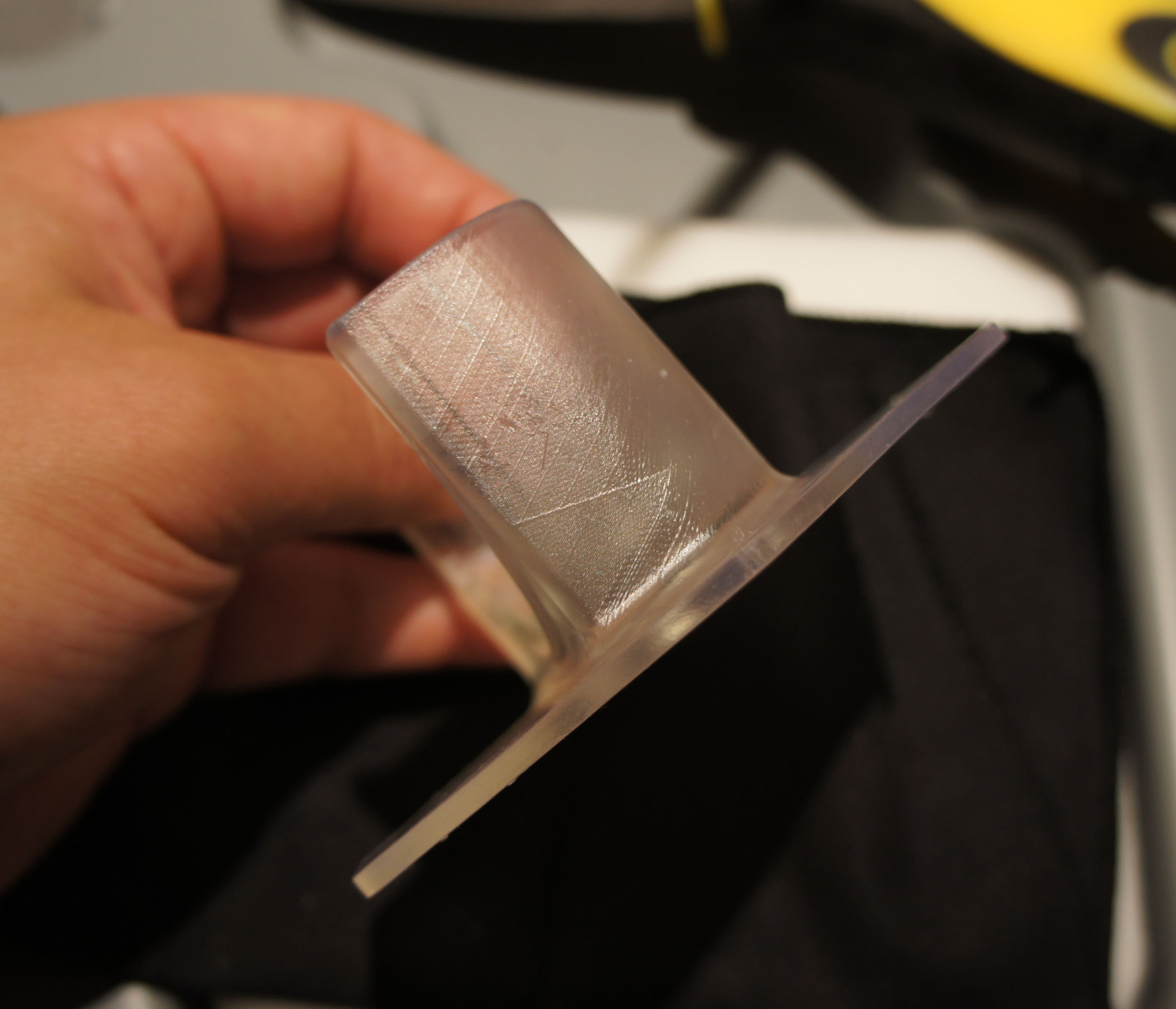
    This particular part features large, robust geometries: it’s designed to be printable on an FDM, so it doesn’t show off the high-resolution capability of the Form 1.

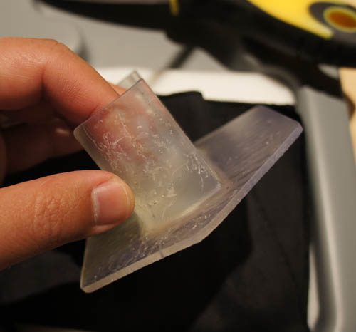
    Small bumps are left on the area where the supports contact the part. These can be sanded off, if necessary.

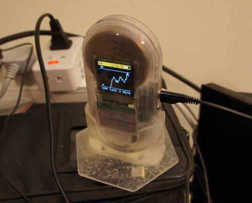
    The print is a success! It fits my Geiger counter like a glove.

    And now for the shameless plug: if you made it all the way through this tear-down, and you’re a top-notch EE, you might want to consider applying for Formlabs’ Electrical Engineering Lead position by dropping them an email with your resume and cover letter.

    Read the whole story
    dmh43
    3991 days ago
    reply
    Share this story
    Delete
    Next Page of Stories